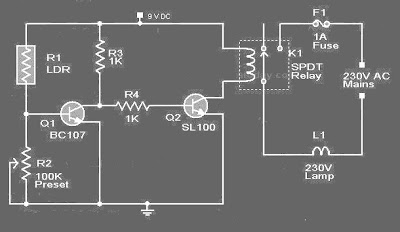
This circuit is of a street light that automatically switches ON when the night falls and turns off when the sun rises. In fact you can this circuit for implementing any type of automatic night light. This circuit can be used to control lights or other electrical equipment with large power to hundreds of watts
The circuit used an LDR to sense the light . When there is light the resistance of LDR will be low. So the voltage drop across POT R2 will be high. This keeps the transistor Q1 ON. The collector of Q1(BC107) is coupled to base of Q2(SL100). So Q2 will be OFF and so do the relay. The bulb will remain OFF.
When night falls the resistance of LDR increases to make the voltage across the POT R2 to decrease below 0.6V. This makes transistor Q1 OFF which in turn turs ON Q2.The relay will be energized and the bulb will glow.
* POT R2 can be used to adjust the sensitivity of the circuit.
* You can use bulb of any wattage ,provided that relay should have the sufficient rating.
* The circuit can be powered from a regulated 9V DC power supply.
* Click Here! to get the power supply circuit for this project.
* The relay K1 can be a 9V SPDT relay.
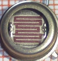
A bout LDR ( Light Dependent Resistor )
Working principle of LDR is the LDR resistance will change with changes in light intensity about it. In the dark resistance of LDR about 10MΩ and in light of 1KΩ or less. LDR is made from semiconductor materials such as cadmium sulfide. With this material the energy of the light that falls cause more load to the electric current is released or increased. This means that the material resistance has decreased.
LDR is used to convert light energy into electrical energy. Automatic light switches and burglar alarms are a few examples of tools that use the LDR. However, because the response to light is slow, LDR is not used in situations where the intensity of light changed drastically.
LDR ( Light Dependent Resistor ) pic


 6:05 PM
 Unknown


 Posted in


0 comments:
Post a Comment