Showing posts with label Radio. Show all posts

Tuesday, March 27, 2012

The circuit is basically a radio frequency (RF) oscillator that operates around 100 MHz. Audio picked up and amplified by the electret microphone is fed into the audio amplifier stage built around the first transistor. Output from the collector is fed into the base of the second transistor where it modulates the resonant frequency of the tank circuit (L1 coil and the trimcap) by varying the junction capacitance of the transistor. Junction capacitance is a function of the potential difference applied to the base of the transistor T2. The tank circuit is connected in a Hartley oscillator circuit.

Components List

R1=220K
R2=4.7K
R3,R4=10K
R5=100ohm
C1,C2=4.7uF Electrolytic
C3,C4=1nF
C5=2-15pF
C6=3.3pF
Q1=BC547C
Q2=BD135
P1=25K
MIC=Electret Condenser Type
P1 act as condenser microphone volume level. For FM, coil will be small. Use thin gauge enamel magnet wire. the diameter of coil will be a couple mm: use ink tube from pen to form, and try 8-12 turns. Small inductance coils make for much guess work.

Sunday, March 25, 2012


This is an mini fm Radio transmitter circuit. The supply voltage is between 1.1 – 3 Volts with power consumption is 1.8 mA at 1.5 Volts. This circuit should be able to cover 30 meters of range max. at 1.5 Volts.

mini FM transmitterSkema rangkaian mini FM transmitter


Note:
* Use a battery for powering the circuit.It will reduce noise.
* An FM antenna from a old radio is a better option than the wire antenna.


PN2222A transistor description

This device is NPN General Purpose Amplifier for use as a medium power amplifier and switch requiring collector currents up to 500mA.

Absolute Maximum Ratings.
  • Collector-Emitter Voltage (VCEO ) : 40 V.
  • Collector-Base Voltage (VCBO) : 75 V.
  • Emitter-Base Voltage (VEBO) : 6.0 V.
  • Collector Current (IC) 1.0 : A.
  • Operating and Storage Junction Temperature Range (TSTG) :- 55 ~ 150 °C.
  • Collector-Emitter Breakdown Voltage : 40 V.
  • Collector-Base Breakdown Voltage : 75 V.
  • Emitter-Base Breakdown Voltage : 6.0 V.
This is a FM transmitter circuit using Maxim semiconductors IC MAX2606. In the circuit the nominal frequency is set to 100 Mhz by inductor L1, (390nH) . The left and right channel audio signals from your source are added by R3 and R4, and attenuated by the POT R2. R2 can be used as a volume control .POT R1 can be used to select a channel of transmission between 88Mhz and 108Mhz.Use 80 cm long wire as the antena.

Pemancar Fm 88-108MhzSkema Rangkaian Pemancar Fm 88-108Mhz


Note:
* Use a battery for powering the circuit.It will reduce noise.
* An FM antenna from a old radio is a better option than the wire antenna.


IC MAX2606 Description

The MAX2605-MAX2609 are compact, high-performance intermediate-frequency (IF) voltage-controlled oscillators (VCOs) designed specifically for demanding portable wireless communication systems. They combine monolithic construction with low-noise, low-power operation in a tiny 6-pin SOT23 package.

These low-noise VCOs feature an on-chip varactor and feedback capacitors that eliminate the need for external tuning elements, making the MAX2605-MAX2609 ideal for portable systems. Only an external inductor is required to set the oscillation frequency. In addition, an integrated differential output buffer is provided for driving a mixer or prescaler. The buffer output is capable of supplying up to -8dBm (differential) with a simple power match. It also provides isolation from load impedance variations.

The MAX2605-MAX2609 operate from a single +2.7V to +5.5V supply and offer low current consumption. These IF oscillators can cover the 45MHz to 650MHz frequency range.

Pin IC MAX2606
IC MAX2606 Absolute Maximum Rating
  • VCC to GND..............................................................-0.3V to +6V
  • IND to GND ................................................-0.6V to (VCC + 0.3V)
  • TUNE to GND .............................................-0.3V to (VCC + 0.3V)
  • OUT+, OUT- to GND ..................................-0.3V to (VCC + 0.6V)
  • Continuous Power Dissipation (TA = +85°C)
  • 6-Pin SOT23 (derate 8.7mW/°C above +70°C)...........696mW
  • Operating Temperature Range ...........................-40°C to +85°C
  • Junction Temperature......................................................+150°C
  • Storage Temperature Range .............................-65°C to +150°C
  • Lead Temperature (soldering, 10s) .................................+300°C
Here is a FM radio circuit using IC7400. IC TDA7000 is a monolithic integrated circuit for mono FM portable radios, where a minimum on peripheral components is crucial. The IC TDA7000 has a Frequency-Locked-Loop system with an intermediate frequency of 70 kHz. The intermediate frequency selectivity is achieved by active RC filters. The only function which needs alignment is the resonant circuit for the oscillator, thus selecting the reception frequency. Spurious reception is avoided by means of a mute circuit, which also eliminates too noisy input signals. Special steps are taken to meet the radiation requirements

Penerima Radio FmSkema Rangkaian Penerima Radio Fm


• L1 and L2 wind 5 turns of 0.6 mm enameled Copper wire on a 4 mm dia plastic former.


IC TDA7000 Description

The TDA7000 is a monolithic integrated circuit for mono FM portable radios, where a minimum on peripheral components is important (small dimensions and low costs).
The IC has an FLL (Frequency-Locked-Loop) system with an intermediate frequency of 70 kHz. The i.f. selectivity is obtained by active RC filters. The only function which needs alignment is the resonant circuit for the oscillator, thus selecting the reception frequency. Spurious reception is avoided by means of a mute circuit, which also eliminates too noisy input signals. Special precautions are taken to meet the radiation requirements.
IC TDA7000Lay out IC TDA7000


Data IC TDA7000

Supply voltage range: 2,7 to 10 V
Supply current : 8 mA
R.F. input frequency range: 1,5 to 110 MHz
Sensitivity for -3 dB limiting
• (e.m.f. voltage)
• (source impedance: 75 Ohm mute disabled) EMF: 1,5 uV
Signal handling (e.m.f. voltage)
• (source impedance: 75 Ohm) EMF typ. 200 mV
A.F. output voltage at RL = 22 kOhm75 Mv

Supply voltage: max. 12 V
Oscillator voltage: 0,5 to VP0,5 V
Storage temperature 55 to 150 C
Operating ambient temperature 0 to 60 C.

Saturday, March 24, 2012

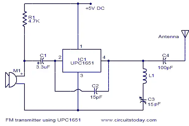
fm-transmitter-using-upc1651Here is the circuit diagram of an FM transmitter using the IC UPC1651. UPC1651 is a wide band UHF Silicon MMIC amplifier. The IC has a broad frequency response to 1200MHz and power gain up to 19dB.The IC can be operated from 5V DC.
The audio signals picked by the microphone are fed to the input pin (pin2) of the IC via capacitor C1. C1 acts as a noise filter. The modulated FM signal will be available at the output pin (pin4) of the IC. Inductor L1 and capacitor C3 forms the necessary LC circuit for creating the oscillations. Frequency of the transmitter can be varied by adjusting the capacitor C3.


Notes.
  • The circuit can be assembled on a Vero board.
  • Inductor L1 can be made by making 5 turns of 26SWG enameled copper wire on a 4mm diameter plastic former.
  • A ¾ meter insulated copper wire can be used as the antenna.
  • Do not give more than 6V to the IC.
  • Mic M1 can be a condenser microphone.

Friday, March 23, 2012

This FM transmitter circuit uses four radio frequency stages: a VHF oscillator built around transistor BF494 (T1), a preamplifier built around transistor BF200 (T2), a driver built around transistor 2N2219 (T3) and a power amplifier built around transistor 2N3866 (T4).

FM Transmitter circuit diagram

A condenser microphone is connected at the input of the oscillator. Working of the 1 Watt transmitter circuit is simple. When you speak near the microphone, frequency-modulated signals are obtained at the collector of oscillator transistor T1.

The FM signals are amplified by the VHF preamplifier and the pre-driver stage. You can also use transistor 2N5109 in place of 2N2219. The preamplifier is a tuned class-A RF amplifier and the driver is a class-C amplifier. Signals are finally fed to the class-C RF power amplifier, which delivers RF power to a 50-ohm horizontal dipole or ground plane antenna.
Use a heat-sink with transistor 2N3866 for heat dissipation (Note: or 2N4427 because it works better at 12 V and delivers up to 1 watt RF power). Carefully adjust trimmer VC1 connected across L1 to generate frequency within 88-108 MHz. Also adjust trimmers VC2 through VC7 to get maximum output at maximum range.
Regulator IC 78C09 provides stable 9V supply to the oscillator, so variation in the supply voltage will not affect the frequency generated. You can also use a 12V battery to power the circuit. Assemble the circuit on a general purpose PCB. Install the antenna properly for maximum range.
Coils L1 through L5 are made with 20 SWG copper-enamelled wire wound over air-cores having 8mm diameter. They have 4, 6, 6, 5 and 7 turns of wire, respectively.

Thursday, March 22, 2012

Rangkaian 3V FM Transmitter
Skema Rangkaian 3V FM Transmitter
This 3V FM transmitter is about the simplest and most basic transmitter to build and have a useful transmitting range. It is surprisingly powerful despite its small component count and 3V operating voltage. It will easily penetrate over three floors of an apartment building and go over 300 meters in the open air.

The circuit is basically a radio frequency (RF) oscillator that operates around 100 MHz. Audio picked up andamplified by the
electret microphone is fed into the audio amplifier stage built around the first transistor. Output from the collector is fed into the base of the second transistor where it modulates the resonant frequency of the tank circuit (the 5 turn coil and the trimcap) by varying the junction capacitance of the transistor. Junction capacitance is a function of the potential difference applied to the base of the transistor. The tank circuit is connected in a Colpitts

Place the transmitter about 10 feet from a FM radio. Set the radio to somewhere about 89 - 90 MHz. Walk back tothe FM transmitter and turn it on. Spread the winding of the coil apart by approximately 1mm from each other. No coilwinding should be touching another winding. Use a small screw driver to tune the trim cap. Remove the screwdriverfrom the trim screw after every adjustment so the LC circuit is not affected by stray capicitance. Or use a plasticscrewdriver. If you have difficulty finding the transmitting frequency then have a second person tune up and downthe FM dial after every adjustment. One full turn of the trim cap will cover its full range of capacitance from 6pF to 45pF. The normal FM band tunes in over about one tenth of the full range of the tuning cap.

So it is best to adjust it in steps of 5 to 10 degrees at each turn. So tuning takes a little patience but is not difficult. The reason that there must be at least 10 ft. separation between the radio and the FM transmitter is that the FM transmitter emits harmonics; it does not only emit on one frequency but on several different frequencies close to each other. You should have little difficulty in finding the Tx frequency when you follow this procedure.

Tuesday, March 20, 2012

 Pemancar TV
Skema Rangkaian Pemancar TV Sederhana
This Transmitter Circuit TV uses standard 1 FM modulation for sound and PAL for video modulation. Audio signal will be modulated is pre-amplified using the transistor Q1 and associated components. The transistor Q2 has two jobs: production of carrier frequency and modulation. The pre-amplified audio signal is fed to the base of transistor Q2 for modulation. Capacitor C5 and inductor L1 forms the tank circuit which is responsible for producing the
carrier frequency. The video signal is fed to the emitter of transistor Q2 via POT R7 for modulation. The modulated composite signal (audio+video) is transmitted by the antenna A1.


Inductor L1 can be made by making 4 turns of 24SWG enameled copper wire on a 6mm dia: plastic former. T1 can be a radio frequency transformer with built in capacitor. (Can be found on old transistor radio boards). Antenna A1 can be a 1M long copper wire. (Experiment with the length to get optimum performance). This transmitter is working in VHF band somewhat between 50 – 210MHz. This transmitter is compatible only with PAL B and PAL G systems.

List Componet:
R1 = 10KOhm R2 = 47KOhm R3 = 15KOhm R4 = 8.2KOhm R5 = 47KOhmR6 = 47KOhm R7 = 1Kohm resistor variable R8 = 75Ohm C1 = 10uF/25Volt capacitor electrolik C2 = 0.001uf/10nF capacitor ceramic C3 = 100nF C4 = 10nf C5 = 47pF (variable capacitor) C6 = 10nF C7 = 10pF C8 = 27pF c9 = 100nF C10 = 470uF c11 = 10nF C12 = 220uF/25Volt Q1 = BC547 NPN transistor Q2 = BC547 NPN transistor
T1 = T1 can be a radio frequency transformer with built in capacitor. (Can be found on old transistor radio boards).
L1 = 4 turns of 24SWG enameled copper wire on a 6mm dia: plastic former.

Thursday, March 15, 2012


The advantages of FM modulation is free from the influence of air disturbance, the bandwidth (wide band) is larger, and the high fidelitas. If compared with the AM system.

fm transmitter is a modification of the fm transmitter on the market (type of saturn s 038). with several series of modifications and additions boster series can produce power at around 12 watts


try in the series after this work is quite good, the signal generated is stable and strong enough
up time should not in a hurry to do directly, but overall do each part in sequence so that the error may be earlier

the first part of the work is in the oscillator, after the raft can try in turn to the way radio waves on the free and set the radio volume so clearly audible hissing sound. turn up the core koker hissing sound on the radio is missing, if you get a signal in a robust and stable means that the set of oscillator has been working with both.

the next section can start at the raft, after finished the second set trimer (C8 and C11) in the buffer in turn can power up in most large and most small SWR. If the series works well, will produce approximately 0.25 watt power

to get more resources than most can add more series boster 12 watt range, so the distance will be increased to reach 7-fold


12 watt Boster Circuit FM transmitter