Showing posts with label Home Circuits. Show all posts

Wednesday, April 18, 2012

Here is a simple freezer alarm circuit, but ultra sensitive with a buzzer. The circuit raises an audio alert when the temperature inside the freezer box goes up above a preset level. The circuit requires 9V dc supply and can power from a standard 9V alkaline battery.
A negative temperature co-efficient type (NTC type) small thermistor (R1) here works as the freezer status sensor. Related components (T1 and T2) are used to drive a 6 to 9V rated mechanical buzzer. When the sensor detects a temperature shoot, the buzzer starts beeping and remains in that condition, till power to the circuit is removed. For this on/off plus reset function any small dc toggle switch can be inserted at the positive rail.

Skema Rangkaian Alarm Freezer
Skema Rangkaian Indikator Ketinggian Air

By means of a Relay, employed to drive a water pump, this circuit provides automatic level control of a water reservoir or well.

Skema Rangkaian Indikator Ketinggian Air


Note:
  • The two steel rods must be supported by a small insulated (wooden or plastic) board.
  • The circuit can be used also with non-metal tanks, provided a third steel rod having about the same height of the tank will be added and connected to the circuit's negative ground.
The shorter steel rod is the "water high" sensor, whereas the longer is the "water low" sensor. When the water level is below both sensors, IC1C output (pin #10) is low; if the water becomes in contact with the longer sensor the output remains low until the shorter sensor is reached. At this point IC1C output goes high, Q1 conducts, the Relay is energized and the pump starts operating.
Now, the water level begins to decrease and the shorter sensor will be no longer in contact with the water, but IC1C output will be hold high by the signal return to pin #5 of IC1B, so the pump will continue its operation. But when the water level falls below the longer sensor, IC1C output goes low and the pump will stop.
SW1 is optional and was added to provide reverse operation. Switching SW1 in order to connect R3 to pin #11 of IC1D, the pump will operate when the reservoir is nearly empty and will stop when the reservoir is full. In this case, the pump will be used to fill the reservoir and not to empty it as in the default operating mode.

List Component
  • R1,R2: 15K 1/4W Resistors
  • R3: 10K 1/4W Resistor
  • R4: 1K 1/4W Resistor
  • D1: LED
  • D2: 1N4148 Diode
  • IC1: 4001
  • Q1: BC337 NPN Transistor
  • SW1: witch
  • RL1: Relay with SPDT 2A @ 230V switch, Coil Voltage 12V

Friday, April 6, 2012

Gambar 1. Skema Rangkaian Level Air
Rakaian level air adalah rangkaian elektronika yang berfungsi untuk mendeteksi tingkat ketinggian air yang mana pada level tertentu akan menghidupkan pompa air secara otomatis. Sehingga dengan bantuan alat ini anda tidak perlu sibuk untuk menyalakan atau mematikan pompa air pada saat penampungan penuh ataupun kosong. Mungkin kalau hanya
untuk keperluan rumah tangga skala kecil, rangkaian level air ini tidak terlalu berguna. Tetapi jika untuk keperluan yang lebih besar seperti industri rumah tangga dan pabrik-pabrik skala besar maka alat ini akan menjamin ketersediaan supply air kapanpun dibutuhkan. Hal ini karena bak penampungan ataupun tedmont akan selalu berada pada posisi yang selalu tersedia air.
Prinsip kerja dari rangkaian level air ini cukup sederhana yakni mengkondisikan supaya air selalu tersedia didalam bak penampungan dengan menyalakan pompa pada saat air akan habis dan mematikan pompa pada saat bak penampungan telah penuh. Tugas untuk mengetahui posisi air di dalam penampungan adalah dilakukan oleh 4 buah kawat level sebagai sensor (pada gambar 2). Ke-empat kawat tersebut diposisikan bertingkat dari yang berada mendekati dasar penampungan hingga pada posisi teratas. 
 
Gambar 2. Kawat Probe
Komponen yang dibutuhkan untuk rangkaian level air atau pompa air otomatis :
Resistor :
R1 : 100K
R2 : 100K
R3 : 100K
R4 : 2,2K
R5 : 2,2K
R6 : 2,2K
R7 : 10K
R8 : 100K
R9 : 1 K
R10 : 10K
R11 : 220 Ohm
R12 : 220 Ohm
R13 : 4,7 K
Kapasitor :
C1 : 0,01 uf
C2 : 100 uf
Transistor :
Q1 sd Q4 : BC 546
Q5 & Q6 : PN 2222
Dioda :
D4 : IN4007
Led : D1 sd D4
Integrated Circuit
IC NE555
Relay 9 volt 
Pompa Air

Catatan :
  • Power Supply yang digunakan adalah DC 12 Volt
  • Probe dibuat dengan menggunakan 4 utas kawat ( kawat : A, B, C dan D )
  • Pompa air sesuai kebutuhan
  • Relay 9v atau 12v yang digunakan hendaknya mempunyai dispasi daya yang cukup untuk mensaklarkan besarnya arus motor listrik jala2 PLN 220 Vac.

Saturday, March 31, 2012

A clap switch circuit is a classic beginner’s project. Equipment can be switched on and off by just clapping your hands. Add a tiny microcontroller and you can easily build-in some more useful features.
The microcontroller in this circuit makes it a simple job to add some useful features that are not seen on other clap switch designs:


– Changeover relay contacts enable the unit to be wired in conjunction with a manual changeover switch so
that manual override of the switched equipment is always possible.
– The unit is only responsive to a specific sequence of sounds i.e., two claps within a defined time window.
– A safety feature masks the input for a given time window if misuse (repeated commands) is detected (useful if children have discovered how it works).
The safety feature and two-clap sequence detector can be built using TTL or CMOS flip-flops but by using a single microcontroller the circuit can be greatly simplified. A mains power supply is included so no additional power source is required.
The Microchip flash PIC12F629 microcontroller is a neat device; the small 8-pin package contains a complete microcontroller including clock generator, reset circuitry, Flash ROM, RAM and EEPROM. Two of the eight pins are used for the supply connections while the remaining six are general-purpose I/O pins. A few of these pins have special function like the comparator inputs. The sound sensitivity of the circuit can be adjusted by programming the comparator threshold level in software.

Clap switch COMPONENTS LIST:
Resistors:
R1,R6,R7 = 4kΩ7
R2 = 150kΩ
R3 = 22kΩ
R4 = 10kΩ
R5 = 150Ω
P1 = 100kΩ preset H
Capacitors:
C1 = 220μF 25V radial
C2 = 100nF
C3 = 1μF 16V
Semiconductors:
B1 = B80C1500 (round case, 80V piv, 1.5A)
D1,D2 = 1N4148
D3 = bicolour LED (red/green)
IC1 = 78L05
IC2 = PIC12F629CP, programmed
T1,T2,T3 = BC238 or BC547
Miscellaneous:
JP1 = 2-way pinheader with jumper
K1 = 2-way PCB terminal block, lead pitch 7.5mm
K2 = 3- way PCB terminal block, lead pitch 7.5mm
MIC1 = 2-terminal electret microphone capsule
Re1 = bistable relay, 2 x changeover (e.g., Schrack RT314F12)
Tr1 = mains transformer 1 x 6V, min. 2VA, short-circuit proof (e.g., Marschner VN30.15/10522 or Era 030-7340.0T; Conrad Electronics # 506141)

Monday, March 26, 2012

Rangkaian ini akan mengeluarkan frekwensi 22 KHz yang akan membuat serangga serangga merasa terganggu, sehingga rangkaian ini bisa digunakan untuk mengusir serangga, baik di rumah maupun di sekeliling rumah anda. Rangkaian ini menggunakan CMOS 4047 sebagai komponen inti. Untuk hasil yang lebih baik, sebaiknya gunakan eksternal power suplly.


Daftar Komponen:

C1............................22 uF
C2............................4n7
IC............................CMOS 4047
Tr1, Tr2...................BC 337
Tr3, Tr4...................BC 327
Pot...........................4k7

Sunday, March 25, 2012

The circuit uses a 555 timer wired as an astable oscillator and powered by the emitter current of the BC109C. Under dry conditions, the transistor will have no bias current and be fully off. However as the probes get wet the transistor will conduct and sounding the alarm.


An On/Off switch is provided and remember to use a non-reactive metal for the probe contacts. Gold or silver plated contacts from an old relay may be used, however a cheap alternative is to wire alternate copper strips from a piece of veroboard. These will eventually oxidize over but as very little current is flowing in the base circuit, the higher impedance caused by oxidization is not important. No base resistor is necessary as the transistor is in emitter follower, current limit being the impedance at the emitter (the oscillator circuit).
This circuit will produce an audible alarm when the water level reaches a preset level.The circuit can be powered of a 3V battery and is very handy to use.


The circuit is based on an astable multivibrator wired around IC1 (NE 555).The operating frequency of the astable multivibrator here will depend on capacitor C1, resistances R1,R2 and the resistance across the probes A&B.When there is no water up to the probes,they will be open and so the multivibrator will not produce oscillations and the buzzer will not beep.When there is water up to the level of probes,some current will pass through the water,the circuit will be closed to some extend,and the IC will start producing oscillations in a frequency proportional to the value of C1,R1,R2 and the resistance of water across the probes.The buzzer will beep to indicate the presence of water up to the level of the sensing probes.


Notes


  • The circuit can be powered of a 3V battery.
  • Assemble the circuit on a good quality PCB or common board.
  • The probes can be made of two insulated copper Aluminiun wires.
  • Place the probes at the position where you have to sense the level.


The electronic dog repellent circuit diagram below is a high output ultrasonic transmitter which is primarily intended to act as a dog and cat repeller, which can be used individuals to act as a deterrent against some animals. It should NOT be relied upon as a defence against aggressive dogs but it may help distract them or encourage them to go away and do not consider this as an electronic pest repeller.


The ultrasonic dog repellant uses a standard 555 timer IC1 set up as an oscillator using a single RC network to give a 40 kHz square wave with equal mark/space ratio. This frequency is above the hearing threshold for humans but is known to be irritating frequency for dog and cats.
Since the maximum current that a 555 timer can supply is 200mA an amplifier stage was required so a high-power H-bridge network was devised, formed by 4 transistors TR1 to TR4. A second timer IC2 forms a buffer amplifier that feeds one input of the H-bridge driver, with an inverted waveform to that of IC1 output being fed to the opposite input of the H-bridge.
For more electronic dog repeller circuits check the related links bellow.

This means that conduction occurs through the complementary pairs of TR1/TR4 and TR2/TR3 on alternate marks and spaces, effectively doubling the voltage across the ultrasonic transducer, LS1. This is optimised to generate a high output at ultrasonic frequencies.
This configuration was tested by decreasing the frequency of the oscillator to an audible level and replacing the ultrasonic transducer with a loudspeaker; the results were astounding. If the dog repellent circuit was fed by a bench power supply rather than a battery that restrict the available current, the output reached 110dB with 4A running through the speaker which is plenty loud enough!
The Dog and Cat repellant was activated using a normal open switch S1 to control the current consumption, but many forms of automatic switching could be used such as pressure sensitive mats, light beams or PIR sensors. Thus it could be utilise as part of a dog or cat deterrent system to help prevent unwanted damage to gardens or flowerbeds, or a battery powered version can be carried for portable use. Consider also using a lead-acid battery if desired, and a single chip version could be built using the 556 dual timer IC to save space and improve battery life.

Thursday, March 22, 2012

Rangkaian Lampu Halaman Belakang. Sebagai bagian dari bangun rumah, halaman belakang biasanya ada. Beragam fungsi serta peran yang dimainkannya. Halaman belakang, menjelma menjadi taman-taman indah nan artistik, penuh sentuhan nilai seni pada rumah yang mewah. Tak jarang, kolam renang dengan air kebiruan menjadi pelengkapnya. Di lain pihak, halaman belakang adalah tempat menimbun perkakas yang tidak penting dari suatu
rumah sederhana yang kelebihan perabot.
Tempat bercengkerama keluarga, menyatukan pendapat, berbagi cerita dan cinta. Wahana menikmati secangkir teh, susu atau kopi panas di pagi hari sambil membaca koran. Di sore hari, halaman belakang bisa menjadi tempat pelepas lelah dan penat setelah seharian bekerja. Kursi malas dengan busa empuk, meja-meja bundar bercita rasa seni, tumpukan koran dan buku, beberapa toples cemilan akan lengkap dinikmati di halaman belakang.
Pada kesempatan kali ini saya akan mengetengahkan dan memperkenalkan sebuah rangkaian, yakni Rangkaian Lampu Halaman Belakang.

Rangkaian ini akan bekerja/berfungsi dari pukul 10 malam sampai pagi. Hal ini membantu untuk memberikan cahaya di halaman belakang guna menghindari binatang malam dan bahkan mencegah upaya pencurian. Rangkaian ini sepenuhnya otomatis dan menggunakan LDR sebagai saklar peka cahaya.
Rangkaian memiliki power supply tanpa trafo  dan rangkaian saklar berbasis waktu. Kapasitor C1, dioda D1 dan kapasitor C2 melalui D4 membentuk bagian power supply. C1 adalah X rated kapasitor AC. Tinggi volt AC berkurang ke tingkat yang lebih aman dengan C1 melalui properti rectance. Dioda D1 melalui D4 membentuk penyearah gelombang penuh untuk mengubah AC ke DC dan kapasitor C2 menghilangkan riak dari DC. Resistor R1 adalah resistor pemeras untuk menghapus saat disimpan dari C1 ketika rangkaian dimatikan. Resistor R2 mengurangi lonjakan arus ke rangkaian.
LDR digunakan di Rangkaian Lampu Halaman Belakang untuk memicu IC1 di saat matahari tenggelam (senja). Hambatan dari LDR sangat tinggi sekitar 10 megaohm  pada waktu gelap dan berkurang sampai 100 ohm di waktu sinar matahari cerah. IC CD 4060 adalah pilihan yang baik untuk aplikasi delay waktu yang lama. IC1 adalah kontra biner dengan sumber osilator internal dan 10 output. Selama siang hari, resistensi dari LDR akan rendah sehingga reset pin 12 dari IC1 tetap tinggi yang menghambat kerja dari IC1. Saat matahari terbenam, resistansi LDR meningkat dan 12 pin reset IC akan membumi dan mulai berosilasi dengan komponen, C3, R4 dan R5.  LED merah bersinar mengindikasikan aktivasi dari IC1. Dengan nilai yang diberikan dari C3, R4 dan R5, pin 1 menjadi tinggi setelah 4 jam, yaitu sekitar 10 malam.

Wednesday, March 21, 2012

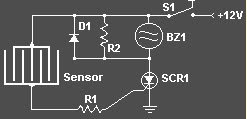
circuit of rain detector uses a sensor made of a small piece of etched PC board and a simple SCR circuit to detect rain and sound a buzzer. The SCR could also be used to activate a relay, turn on a lamp, or send a signal to a security system.
rain detector circuitCircuit of rain detector

Component list of rain detector
  • R1 1K 1/4 W Resistor
  • R2 680 Ohm 1/4 W Resistor
  • D1 1N4001 Silicon Diode
  • BZ1 12V Buzzer
  • S1 SPST Switch
  • SCR1 C106B1 SCR 106CY
  • SENSOR
The sensor is a small piece of PC board etched to the pattern showen in the schematic. The traces should be very close to each other, but never touching. A large spiral pattern would also work.

Make sure to use a loud buzzer.

Tuesday, March 20, 2012

Circuit of musik|melody generator you can make using an IC.The UM66 series are CMOS IC’s designed for using in calling bell, phone and toys. It has a built in ROM programmed for playing music. The device has very low power consumption.Thanks for the CMOS technology.The melody will be available at pin3 of UM66 and here it is amplified by using transistor Q1 dan Q2 to drive the speaker.

 Pembangkit Melody MainanSkema Rangkaian Pembangkit Melody Mainan

UM66 is a pleasing music generator IC which works on a supply voltage of 3V. the required 3V supply is given through a zener regulator. its out put is taken from the pin no1 and is given to a push pull amplifier to drive the low impedance lowd speker. A clss A amplifier before pushpull amplifier can be used to decrese the noise and improve out put. UM66 is a 3 pin IC pakage just looks like a BC 547 transistor.

Notes
  • Power supply must be between 6V - 15V .
  • Melody begins from the first note if power is reseted.
  • Assemble the circuit on a good quality common board.


IC UM66 Description
The U66 series is a CMOS LSI designed melody generator IC for use in telephones and toys application. It has an on-chip ROM programmed for musical performance. Produced by CMOS technology, the device results in very low power consumption. And with built-in RC oscillator, a compact melody module can be constructed with only a few additional components.

 IC UM66

Pin No Designation Description
-1. Out put Melody out put
-2. +Vdd Positive power supply
-3. -Vss Negative Power supply

Features of UM66T series
-62 Note ROM Memory
-Voltage rating: 1.3V to 3.3 V
-Power on reset
Ding dong bel Rumah
Skema Rangkaian bel Rumah
This simple circuit an low cost ding dong bell suitable for calling bell purposes. It is made around IC 8021-2 . IC 8021 has an in-built circuitry to produce ding dong sound each time its pin 3 is pulled low. The sound is stored in a 4 bit ROM.a complementary-pair, two-transistor amplifier is used to amplify the sound to a fair level of audibility. A piezo tweeter or an 8-ohm, 500mW speaker can be used at the output.


List Component bel Rumah:
R1: 1K 1/4W Resistance
C1: 10µF/12-25V Electrolytic Capacitance
T1: BC548/c8050 NPN transistor
T2: BC557/C8550 PNP transistor
IC1: 8021-2 ding dong sound generator
Ls1: Speaker tweeter 500 Mwatt - 5 watt
S1: switch on/off
S2: Switch Normally close
B1: 3V Cell
Each time when switch S2 is pressed, ding dong sound is produced twice. If you try to press switch S2 a second time when the first ding dong sound is still being produed, it has no effect whatever and the two ding-dong bell sounds will be invariably produced.S1 is the ON- OFF switch.Assemble the circuit on a good quality all pupose PCB.Don’t forget to use an IC holder for IC 8021.
IC 8021 Description
The 8021-2 is a ding-dong sound effect generator IC produced by LSI CMOS technology. With built-in RC oscillator and digital envelope circuits, minimal external components are required. This IC simulates the mechanical ding-dong sound, and is ideal for door bell application.
IC 8021 Features
- 1.3V to 3.3V operating voltage and low power consumption
- One-shot mode of 2 ding-dong playing sequences
- Standard TO-92 package form
- Dynamic speaker can be driven with external NPN transistor

IC 8021 Absolute Maximum Ratings
DC Supply Voltage ........................................... -0.3V to +5.0V
Operating Ambient Temperature .................... -10°C to 60°C
Storage Temperature ....................................... -55°C to 125°C

Saturday, March 17, 2012

Menyalakan atau mematikan lampu pada umumnya dilakukan dengan menekan saklar. Pada rangkaian ini cukup dengan satu tepukan, lampu akan menyala….untuk memadamkan berikan satu tepukan berikutnya. Selamat mencoba!!

Meski sangat sederhana, lampu lilin elektronik ini sangat unik.

Karena lampu lilin ini dapat dipergunakan sebagai pengganti lilin biasa ketika sedang berulang tahun.
Sangat cocok bagi muda-mudi ataupun pasangan yang menginginkan kejutan dan suasana romantis bagi pasangannya.

Untuk menyalakannya kita hanya butuh menyalakan sebuah korek api, dengan catatan, penerangan ruangan sebelumnya harus dibuat agak redup.
Setelah LDR mendapat cahaya dari korek api, maka akan terjadi perubahan tahanan pada LDR. Sim salabim ...lampu menyala. Kejutan buat si dia.

Untuk mematikan kembali, kita dapat meniup LDR tersebut.

Jika anda dapat mengemas dalam bentuk yang cantik dan menarik, sangat memungkinkan menjadi komoditas yang menjanjikan.


Daftar Komponen :

Trimpot RV ………....….. 100 K
LDR……………………....... TIL-209
TRANSISTOR TR……… BC-108
Saklar Lampu…………… 3,1 V / 0,3 mA
Baterai…………………..... 3 buah

Friday, March 16, 2012

Circuit of Movement detectors

Photodioda as removing the transmitter beam infra red with the pulsation frequency 5KHz, then the pulsation will be reflection by reflector in front of it. and received by the phototransistor as the receiver. The detected object is located between the transmitter-receiver with a reflector.

Circuit on the left is the transmitter modulation circuit that produces infrared 5KHz throbbing. On the right side is the receiver circuit, there is a resonance tuned amplifier. Band width it can control so the receiver circuit can catch the beat of the transmitter modulation 5Khz. Bandwidth control is also working to reduce the sensitivity of the effect of light in the surrounding areas.
A microphone preamp is a preamplifier used to amplify a microphone's low output voltage to a stronger, more usable level. A microphone preamp must provide stable gain for small signals without being sensitive to induced noise from cabling and without distorting large amplitude signals. Most microphones must be used in conjunction with a microphone preamp to function properly.

Simple audio Pre-Amp mic

This circuits use infront an RF oscilator to make an RF transmitter that is very sensitive to sound
This series will work as the lighting will automatically turn on when the voltage net PLN off. If the net voltage on the series will off automatically.
Emergency Light chain scheme can be viewed directly on the image above


Components list:

R1
R2
C1
D1,D2
S1
Tr1
Trafo
L1,l2
Batery
: 33 Ohm
: 470 Omh
: 470 uF/16v
: 1n4001
:
switch (push on push off)
: BC 160 or BC 143
: 4,5 volt 200 mA
: lamp 2,5 volt
: NiCd 2x1,25 volt 2-4 Ah


Series of automatic lighting unit is very simple. Voltage electricity from the net PLN revealed by transformer Tr1 and change in DC with half-wave system by dioda D1 and capacitor C1.
Next portion 6 Volt DC is used to fill the 2 Ni-Cad Battery through R1 and D2 with a continuous flow of about 100 mA (charging current to a safe a Ni-Cad battery 2 Ah).

reverse bias between the base of emitor transistors T1 obtained from the voltage fall on the D2 will make transistors T1 does not work so that lamp will be off. When voltage net PLN suppressed, T1 base transistors will be biased flow through R2, transistors T1 will work and lamp on.

When the voltage net PLN entry, transistors T1 will does not work, the lamp will be off and the battery charged through R1 and D2

Thursday, March 15, 2012

Tikus memang menjengkelkan, apalagi ketika sudah merusak barang kesayangan kita,dan kotorannya yang baunya minta ampun. Dengan alat pengusir tikus elektronik ini dapat membantu anda untuk mengusirnya:

Skema Rangkaian Pengusir Tikus